Thursday, August 28, 2008

Notes on Object Visibility

Object visibility can be controlled in Revit in many ways.

a. Temporary switch on / off:

You can temporarily hide / unhide selected objects or categories in a view using the Hide / Isolate button available in the View tool bar at the bottom of the screen. You can also access this command from View Menu > Temporarily Hide / Isolate or by pressing the relevant shortcuts. The objects that you switch off using this method will still get printed. If you close the project and open the project again, these objects loose their temporary visibility setting.

b. Permanent visibility settings:

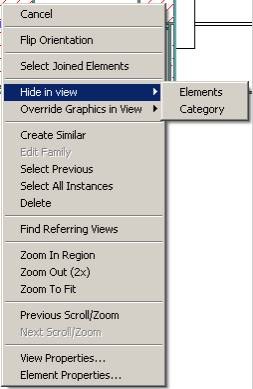
You can select an element and right click and select the Hide in view command to switch on/off an element or all elements that belong to the category of the selected element.
clip_image002
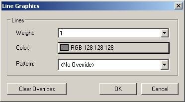
You can select an element and right click and select the Override graphics in view command to change the colors / line thickness / line pattern of the selected element or all elements that belong to the category of the selected element.
clip_image004
You can also change the colors / line thickness / line pattern of these objects, and also switch them on / off using the command menu View > Visibility Graphics. The objects that you switch off using this method will NOT get printed. If you close the project and open the project again, these objects don’t loose their visibility setting. But anything you change will only affect this particular view.

c. View Templates:


If you want more than one view to have the same visibility settings, instead of changing the visibility setting for each view separately one by one, you can use a View Template. We create a view template and just assign it to other views.

· Create a View template:

1. Setup a view to your liking: Scale / shading / detail level / visibility graphics etc.

2. Go to menu View > Create View Template from view…

3. Give it a name and press ok. Now you have created a view template based on the current view. You could apply this setting to any other view later.

· Apply a view template:

1. Go to the appropriate view

2. Go to menu View > Apply View Template

3. Select the relevant “View template” you had created.

4. Press ok.

You can also right click a view or a set of views in the project browser and then select “Apply View Template”.

d. Permanent for the whole model:

To change visibility settings for objects, that affect the whole model, you have to go to menu

· Settings > Objects styles.

You can change the colors / line thickness / line pattern of these objects, but cannot switch them on / off. If you close the project and open the project again, these objects don’t loose their visibility setting. Anything you change will affect the entire model. Objects styles are NOT view specific.

e. Screening:

· To screen an individual element:

1. Select the element;

2. Right click > Override Graphics in View > By Element… ;

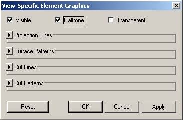
3. then check “Halftone”
clip_image006

· To screen all elements that belong to a category:

1. Select the element;

2. Right click > Override Graphics in View > By Category…;

3. Check “Halftone” for the selected objects category in the Visibility Graphics dialog box.

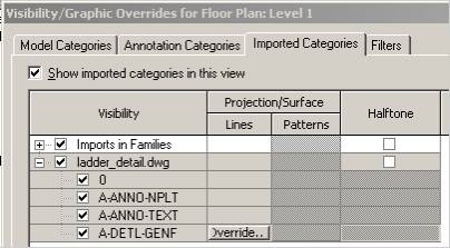
· To screen CAD Files: Similar method listed above. However, if you want to show certain layers in thick lines (like A-Demo layers in a Demo drawing) then instead of Halftoning the whole drawing,

1. Go to VG (View menu >Visibility Graphics)

2. In the Imported categories tab, select all the layers in the DWG except the one you want to make it bold
clip_image008

3. Override the layer color and line weight, etc.
clip_image010

4. Then select the layer you want bolded and override its color / line weight, etc.
f. Surface Patterns:

You can switch on/off, change colors of the surface patterns using the methods described above. If you want to change the surface pattern, you might have to create a new material with a different surface pattern or assign a different material in the property dialog box of the element.

Wednesday, August 27, 2008

Gateway Autodesk User Group Meeting

Here are the details of our next Gateway Autodesk User Group meeting

When: 10th of September - Wednesday - from 6 to 7:30 pm

Where: Masonry Institute, 1429 S Big Bend Blvd, St Louis, MO (google map).

What: "Interoperability between BIM and Building Performance modeling applications like Eco-tect and Green building studio" by Tomislav Zigo

What else: If you are a GAUG member and if you are present at the meeting, you might win a pass to Autodesk University 2008. ($ 1,845 value).

You can RSVP here to make yourself eligible for this AU draw by joining GAUG!!!!

Tuesday, August 26, 2008

Notes on Printing

· Print window

· Duplicate the view; Crop it to suit your needs; then print current view;
It is always a good idea to delete this duplicated view after printing.

· Another workaround is to use the “Print Visible portion of current window option”.
clip_image002

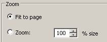
1. If the zoom is set to Fit to Page in the print setup dialog box, Print Visible portion of current window option will print all the visible portion of the current view.

2. If the zoom is set to a zoom scale in the print setup dialog box, and the paper placement option is set to center, revit will print a portion of the model (NOT just the visible portion of the current view) that would fit into the selected size of sheet, in the selected scale, aligning the center point of the view to the center point of the sheet.

3. If the zoom is set to a zoom scale in the print setup dialog box, and the paper placement option is set to offset from corner, revit will print a portion of the model (NOT just the visible portion of the current view) that would fit into the selected size of sheet, in the selected scale, aligning the lower right corner of the sheet to the specified corner from the lower right corner of the view.

· Batch plotting:

1. First, go to the one of the views or sheet that would be included in this batch plotting process.

2. In the print dialog box > Print range option, keep it to Current view.

3. Then go to print setup and set the scale/etc, as if you were printing only this view / sheet.

4. Preview the print.

5. If everything looks ok, then change the Print Range to “Selected view / sheets” and click select button.

6. Always check none before proceeding to build a new batch plot list

7. You cannot preview the batch plot prints. But since you had already previewed it in step 4, you are ok.

8. (If you are uncomfortable with this and really want to preview the whole batch plot set, you need to create DWF or PDF files)

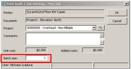
9. In the Print Audit dialog box, you can enter the batch size so that you don’t have to enter the info for every sheet / print.
clip_image004

· Issues

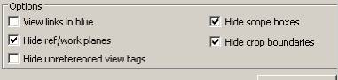
· To print or not to print certain elements, Revit has the following options.
clip_image006

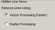
· If you see certain text / hatch objects / tags missing in the printed output (but was visible in the view), then you should select Raster processing. This takes more time (10 secs) but prints properly. Revit defaults to Vector processing.
clip_image008

· If printing crashes your computer or the Print server (no one can print anything to anything!!!@#%$$##!), then use Raster processing. Generally if you want to print a shaded color view from Revit (color shaded plans; rendered views, etc.) always use Raster processing.

· Revit defaults to “Fit to page” option in the Print setup dialog box. You might want to check this always before sending the print. Here zoom 100% would mean that the printed output will have the same scale as that of the View.
clip_image010

· PDF printing;

· Select a PDF printer first. Print setting would be similar to other printers. While making a Batch PDF print, you can combing all PDFs in one file or create separate PDFs for each view / sheet by selecting the option in the print dialog box.
clip_image012

· DWF printing:

· You don’t print to DWF anymore. You go to File menu >Publish DWF to create DWF. Similar to PDFs you can create one combined DWF or separate one for each view / sheet.

Tuesday, August 19, 2008

Color Scheme issue

We had a situation where all the rooms were colored by the color scheme except one. We just could not figure out the reason for this. The room had a column right at the center and a partition wall that is aligned with the column.

After some trial and error, we found out that if we tweak the partition NOT to be aligned with the column the room gets colored! 

image 

Here the partition is aligned.

image 

Here the partition is tweaked.

As long as the partition does not overshoot the column, the room gets colored.

Monday, August 18, 2008

Locking objects and Views

Revit does not have a tool to lock an object or a view. Anybody can delete an object or change the parameters of the view. Revit has a fragile PIN command, which does not allow the 'pinned' object to be edited. But this pinned object can be deleted without much problem. Locking can be achieved, with some mixed results, by employing this cumbersome workaround. The idea is to use an imaginary user to own certain worksets that you don't want everyone to edit.

To lock views:

    1. Close your project.
    2. Go to settings > options and change the username to some imaginary user, for eg. "Locker"
    3. Open the central file
    4. Go to file menu > worksets and switch on view worksets.
    image
    5. Select that particular view and make it editable. The user "Locker" owns that view workset now. (Most of the view related commands will be allowed for other users...including view dependent items!)
    6. Close the central file.
    7. Go to settings > options and change username back to yours.
    8. Open your local file or create a new local and work happily ever after.

If you need to edit the view elements that are locked, you can change the user name, open the project and make edits.

To lock objects:

  1. you can create a workset, for eg. "Locked Workset"
  2. Move any objects that need to be locked to this worksets
  3. Make it editable by the user "Locker", so that others cannot modify it.