Showing posts with label visible. Show all posts

Thursday, January 28, 2010

Turn off grids and levels from linked Revit projects

We link a structural revit project into most of our revit projects. We typically develop the grid and after finalizing it, let our engineers maintain it.

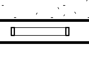
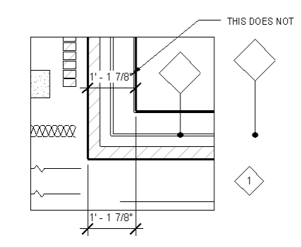
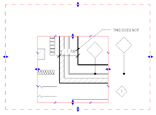
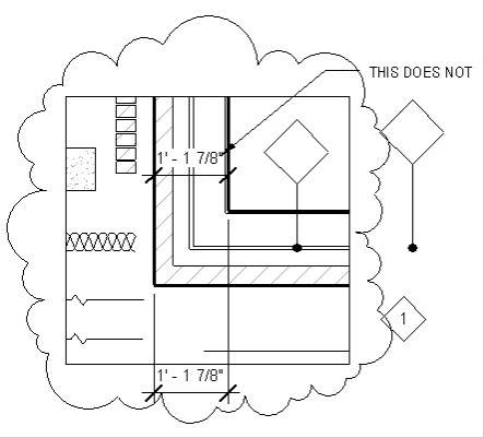
We cannot show their grids in our views because, Revit does not allow the linked grid heads/extension to be tweaked. So, we typically copy/monitor the grids. However, when we tweak the grid heads, we see the linked grid head beneath:

image

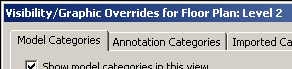
One could go into the visibility graphics, and switch off the grids from the linked file on a view by view basis, but exploiting the workset option is more elegant.

Go to File menu > Manage links… and select the structural model and select ‘Reload From…”

image

and select the same linked structural file. Before pressing ‘open’, select the small arrow next to the ‘open’ button:

image

and select specify. Then press ‘open’. Revit shows the ‘Linking Worksets…” dialog box.

image

Select the ‘Shared Levels and grids’ workset and press ‘close’ and then Ok and again Ok. Now the ‘Shared Levels and grids’ workset from the linked file is closed and is NOT visible in any Revit view. Even though the linked grids are not visible, Revit still ‘monitors it!!!

image

If for some reason you want to see the structural grids, you can repeat the steps above to make them visible.

Monday, January 25, 2010

Structural columns dont show up in detail views

This is a corollary to one of my previous posts: http://revitize.blogspot.com/2009/09/structural-framing-and-plan-display.html

Here is a structural column in the 2nd level plan view. There are two callouts – magenta is of Floor Plan type and the blue is of Detail View type.

image

The column goes from the 2nd level to 3rd level.

image

The respective callout views we get are:

image

and

image

But if the column is changed to span from 1st level to 3rd level like:

image

The column does NOT show up in the detail view type:

image

To make the column visible, you need to edit the family and uncheck the “show family pre-cut in plan views” option in the family category and parameters. More explanation on this here.

It is painful to edit structural families, because when we get the updated structural project from the engr., the family edit needs to be done again. Unless the structural engr does it in their project.

I would really like Autodesk to make this option as the default.

Tuesday, September 1, 2009

Structural Framing and Plan display

When we link a Structural Revit file that has structural bracing into an architectural RVT project,
image
Revit does NOT show the true cut section in the floor plan (based on the view range settings). For eg. the bracing looks like this in plan:

image

However, if we cut a detail section or callout, it looks like:

image

which is the correct representation based on the cut plane and view range.

This is unacceptable. Revit should also show the bracing in plan view types correctly. This can lead to lots of coordination issues. To make Revit display the bracing correctly, ask your structural engineer to

  • Open the steel bracing family.
  • Go to Settings > Family Category and Parameters.
  • Clear the checkbox for "Show family pre-cut in plan views".
    image
  • Reload the family back into the project.
  • After this is done, Revit show the bracing in plan like:

    image

    Even though the architect can edit the structural family to make this change, Architect’s edits in the structural file will be overridden when the structural file is updated next time by the architect. So, it is better if the structural engineer makes the edit it.

    Thanks to Autodesk Subscription team for this tip.

    Wednesday, July 29, 2009

    Switch on and off elements and invisible text

    In one of our projects we had some ‘owner furnished contractor installed’ (OFCI) equipments. We didn't want to show these elements in our contract drawings, but also wanted the ability to show them for client meetings, etc. The building is more than 10 floors, and there were 100s of such equipments strewn around.

    image

    The best way to achieve this would be to create a separate workset for these equipments, and when you switch off the workset (File menu > Worksets) these elements, along with their tags, get turned off.

    The problem is our project was not setup this way. Even though we placed all the objects in a new workset, the tags didn't get turned off, because they were not really tags but dumb texts!!  Text objects belong to the view workset and so, could not be placed in the newly created workset.

    So, we were looking for a workaround. One solution was to create a new text style with almost white color (254, 254, 254) and no leader.

    image

    We assigned all the texts related to these OFCI equipment to this text style to switch them off!  We have to just redefine the text style to make them visible again.

    It still would have been better if we were aware of this requirement while setting up the project!

    Thursday, April 2, 2009

    duplicated dependent view loses some detail callout tags

    When we duplicate a view as dependent, Revit does not show all the detail callout tags / detail section view tags in the dependent view. For eg. when the follwoing view

    image

    is duplicated as dependent, we lost the left (shorter)detail tag as shown below.

    image

    The culprit is the combination of annotation crop and reference view tags!
    Even though the primary view has its annotation crop turned off,

    image

    Revit switches ‘on’ the annotation crop for the dependent duplicated view as shown below.

    image

    To bring back the lost detail tag, we just need to make the annotation crop a bit bigger. (Revit is a bit unforgiving here – even if the annotation crop is big enough to engulf the tag extent, Revit hides it. We need to make the anno crop bigger to make it show.)

    image

    The annotation crop only affects the tags that represent Reference Views. Other normal view tags are not affected because Revit does not consider them ‘strictly’ annotation objects! But Reference view tags are considered as annotation objects (Only duplicating with details brings the reference tags! Duplicating a view does not; In this case the reference tag is NOT hidden, it just is NOT there! )

    Friday, February 6, 2009

    Walls to the underside of the ceiling in RCP

    By default the cut plane is 7’6” for the RCP. Because of this, the walls that go to the soffit of the ceiling (at 8’) are cut and shown as such.

    image

    Theoretically this is right but confuses the contractors who dont understand the ceiling is continuous. The ceiling seems to be terminated by these “walls in section”.

    To make the graphics look “correct”, we:

    1. Created a filter to segregate these walls.
    2. Applied it to a RCP view and tweaked the display to be dashed and transparent.
    3. Created a View template based of this view.
    4. Applied this template to all the other 20 RCPs.

    In detail:

    1. Create a filter (settings menu > Filter) for all walls that have the letter “g” in the value of their Type Mark parameter. (We used the type mark for our wall tags, eg. B3g, which indicated that the partition stopped at the underside of the ceiling.)
      image
    2. Apply this filter to a RCP view in its visibility graphics dialog box. Change the cut lines to be dashed and filter to be Transparent.
       image 
    3. Create a view template based on this view. (View menu > Create a view template from view). Uncheck all the parameters in the ‘include’ column except the VG Overrides Filter.
      image
    4. Select all the RCP views in the project browser, right click and select “Apply View Template…” 
      image
      and apply the newly created view template.
    5. (If you have already created a View Template for all your RCP views, and have applied it as the default view template for RCP views,  you dont want to  apply this truncated View Template. Instead you can edit your existing RCP view template to include the new filter and then “Apply Default View Template” command in the previous step)

    Thursday, January 22, 2009

    INSERTED ELEMENT DISAPPEARS

    Last year I wrote this list to check for any missing objects in Revit.

    This is similar. Sometimes, when we try to insert an element, Revit does not show the inserted object, but shows a small warning message at the bottom right. Here are some reasons that could cause this:

    Visibility Graphics: If the category of the element being inserted is switched off in the VG dialog, this can happen. Instead of inserting the element again and again to check if the element dramatically comes into life, it is better to check the VG.

    Worksets switched off: Advanced users use worksets to manipulate the visibility of a whole set of objects. If the current workset is turned off (File > worksets) then any inserted object wont be visible. It is a good idea to check if the workset is switched off in the VG dialog box, workset tab.

    image

    Phases: If you have contradictory phase filters assigned to a view (View properties > phase filter parameter), that can interfere with the visibility of the inserted object.

    image

    Workplane: If some smart person has changed the workplane, that can affect the visibility of inserted objects. This can happen in RCP. (any model object ‘copied and pasted’ from floor plan view, would get pasted with respect to the floor level and may be behind the cut plane or farther than the view range.

    Wednesday, December 31, 2008

    Elevation Tag Not Visible

    Another quirkiness in Revit.

    Here is a simple project, with a cropped view. Two of the elevation tags are missing.

    image

    When I uncrop the view, the elevation tag show up like:

    image

    The elevation tags themselves are within the crop boundary. When I select the triangle of the elevation tag, Revit shows the elevation cut line and extent that are lying outside the crop boundary like:

    image

    Ironically, this happens irrespective of the annotation crop boundary, for eg.:

    image

    Also, if the Elevation cut plane extends beyond the annotation crop, but the no problem – Revit still shows it.

    image

    The Lesson:

    The elevation tag will show as long as its cut plane cuts through the view crop boundary. (this is the same as other views) The cutline itself is not affected by the annotation crop boundary. (But the elevation tag is affected by the annotation crop boundary)

    One has to move the elevation cut plane so that it passes through the view boundary to make the elevation tag visible.

    Friday, November 7, 2008

    deleting views deletes details along

    In continuation to yesterday's blog,

    If a view is deleted, Revit gives a warned like this sometimes:

    image

    Revit basically lists all the callout views that were created in this deleted view. For eg. when you create a callout view in a view called 'xyz', Revit assigns the view 'xyz' as the callout view's parent. And when the parent view gets deleted, the callout view is also get deleted.

    image

    If you dont want this to happen, you can change the Parent View parameter to none in the callout view's property.

    image

    Changing this value automatically changes the Far clip settings to 'independent' and the 'Show in' parameter to 'intersecting views'

    image

    Now deleting the parent view will not delete these callouts.

    (just to irritate you, now, if you changed the value of the 'show in' parameter to "none" then the callout tag wont be visible in any views...!)

    That brings us back to the best practices: It is always good to create callouts from the Primary view or in just one dedicated view, which you might never have to delete.

    Thursday, November 6, 2008

    Dependent Views and callout tags

    I wrote sometime back about dependent views.

    Here is another quirk.

    It was my understanding that all the annotation objects are synced among all the dependent views and its Primary view. (This rule does not apply to "Element Hide".) The idea was that you could add annotation in any view, and as long as the annotation crop does not crop it, the annotation will be visible in other views.

    When we create a new callout view from one of the dependent views, the callout tag is not visible in other dependent views and in the primary view. That's a bummer.

    However, if you change the value of the "Show In" parameter in the view property to "Intersecting views" from "Parent View only" like

    image

    then the callout tag shows up in other views.

    Ironically, this works only for the callout view type 'Detail'. If the callout view type is 'Floor Plan', this 'show in' parameter is not available. You cannot convert a Floor Plan view type to a Detail type too.

    Any other view type created, like elevation, sections, etc. are visible in all relevant views. They don't have this affliction.

    Also, if you create any view type (including callouts) in the Primary view, those will be visible in all relevant views. Looks like the best practice is to create any necessary view in the primary view only.

    Wednesday, October 8, 2008

    View Range and cut plane revisited

    I read a very nice chart posted on the web (By James Van?) explaining the view range options accessed from the View property. I could not find it anymore and had to make a similar one to explain to our people.

    image

    The TOP range has always been confusing. Symbolic lines / model lines of elements (for eg. windows) that are above the cut plane, but below the TOP range will show up. Seems like the view is aware of some selected objects in between these ranges, but show them only if it is designed to show inside the family. This option can be used to show upper storey windows / over the head casework.

    The <Beyond> linetype can be tweaked in Settings menu > Linetypes... dialog box.

    Here is a window at 3' sill level on a view with a cut plane at 4' and a TOP range of 7'-6" (default)

    image

    The sill level of the window is raised to 7'

    image

    If the sill level is raised to 8', poof...

    image

    The following picture shows the model lines that are used to depict the frame in the window family.

    image

    Monday, September 15, 2008

    Visibility graphics and dependent views

    The Trainers conundrum:

    We have model elements and then annotation elements in Revit. Annotation elements are view dependent and don't show up neither synchronized in other views. And VG is always view dependent. Great!
    image

    We also have dependent views, where the annotation elements are synchronized among other dependent views and are not strictly view dependent . The VG tweaks are the same for the parent and all its dependent views. However the dialog box still says "Overrides for dependent view!", which is not entirely correct.

    image

    Then we have this amazing ability to hide a particular object using the "Hide in View >Elements" option in the right click menu:

    image

    This hides the object only in that view and not in it's synchronized dependent / parent views. Even though this looks little counter intuitive, this behavior is very useful.

    Friday, September 12, 2008

    Crop region and Annotation crop

    Here is a view that has annotation crop shown in green; the view crop is shown but the view is not cropped.

    image

    After the view is cropped, it looks like:

    image

    The View crop (boundary) crops the

    • model elements
    • detail components
    • repeating details
    • filled regions
    • Insulation, etc.
    • detail lines

    It does not crop:

    • annotation tags
    • Text objects

    The annotation crop crops both the text and annotation tags.

    Dimensions - get cropped by both the view crop as well as the anno crop. If any one of the witness points of a DIM is not within the view crop region, then Revit does not show that particular string. And if the DIM string extends beyond the anno crop, it is not shown.

    image

    If we want to draw anything outside the view crop boundary, it is not possible. (One can draw stuff on sheet!) There may not be any circumstances that require it. However, Revit allows us to draw Revision clouds outside the boundary. (Thank God!)

    image

    Quite nuantic!