Showing posts with label CAD links. Show all posts

Tuesday, July 22, 2008

Half tone specific layers in linked CAD

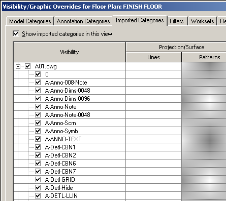
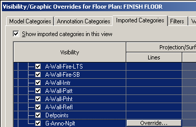
In our office we don't model existing structures. We just use the CAD file to show the existing building for various reasons. We typically halftone the DWG to represent the existing phase. We do it in the VG > Imported categories.

image

While doing the Demo Plan, it gets tricky because we need to highlight the demo objects. Usually we place these objects in the Demo layer and make the linetype of this layer BOLD and DASHed. To show specific layers in different linetype/thickness, we cannot apply the Halftone at the DWG level. These have to be applied at the layer level. To achieve this,

  1. Uncheck the haltone box.
  2. Click on the plus + sign to reveal all the layers in the dwg.
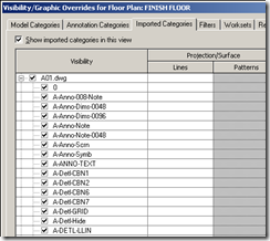
    image
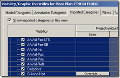
  3. Select all the layers with shift + click. and then select override to override all the layer colors to halftone.
    image
  4. After this, one can select specific layers (like our Demo layer) and override it with other linetypes / colors, etc.
Wednesday, May 21, 2008

Revitizing CAD details

Before going any further:

The best detail is the one created in revit using Detail components and repeating details, revit text, leaders, etc. It is always better to ‘link’ the CAD detail and draw over this CAD detail to create a full blown revit detail and then unlink the CAD detail. If you cannot do this for some reason, think again. If you still cannot do this, then:

To do in CAD:

  • • You can skip the CAD part if you are going to fully explode the detail in Revit.
  • • Run ‘REVIT’ command (this custom command created using LISP, changes our standard DIM style; TEXT style, etc to be revit friendly. It tries to remove stacked text to regular text in DIMs, etc.)
  • • Delete unnecessary stuff. Purge.
  • • Bring objects closer to 0,0,0
  • • Set scale (this custom command created using LISP, sets DIMSCALE; LTSCALE; etc.)
  • • Use the DIM > update to update all the dimensions. This should remove all stacked text in Dimensions. (Revit 2009 does NOT understand stacked text yet!)
  • • Edit Mtext
  • • Unstack dims
  • • Mtext wrap width has to be set correctly in CAD. Because of the change in TEXT style, the width could be wrong – overlapping over drawing elements.
  • • All text within the mtext should have the same color. Revit creates separate text objects for each different colored texts.
  • • Save

To do in Revit:

  • • Open a new project > create a drafting view in a relevant scale and import the CAD detail. Don’t import any CAD detail directly into the project file. It is just good practice!
  • • Full Explode Imported CAD detail
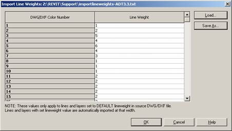
  • • Line thickness should be fine, as long as, File menu > Export/Import settings > import lineweights is setup per your office standard.
  • clip_image002
  • • Revit creates separate linetypes for each layer in the CAD dwg.  You might have to swap them to revit linetypes by selecting the objects with the filter tool. It is easy, as long as the CAD file had followed a layer standard in CAD .
  • • Text style can look a bit different. You have to swap CAD text style names to Revit text styles. Again, this is easy, as long as the CAD file had followed a standard in CAD. All leaders are exploded. You have to select and delete them and create new leaders within Revit. This is painful. The new revit leaders need to point to correct objects!
  • • Hatch may not be present; Typically you want to select the CAD hatches and swap it with Revit filled regions.
  • • Dimensions come as exploded objects. It is better to create new ones in Revit. If line is off the axis, it is difficult to dimension in Revit.
  • • None of the exploded CAD objects should have any remnants of any CAD hatch patter, text style, dwg blocks (arrow heads...!) etc.
  • • Now these objects (or the drafting view) can be copied and pasted into your project.

As I said in the beginning, instead of going through all these steps, one could have easily created a full blown revit detail.

Keeping the details as CAD objects, and linking them in Revit is ok as long as

  1. you have both the licenses of AutoCAD and Revit
  2. You can live with CAD details and RVT details looking little bit different
  3. You are ok fighting with Revit to make it show the CAD hatches,  stacked text, etc properly.

Thursday, March 13, 2008

Updating CAD links in Revit

Revit help files says that a linked CAD files will automatically update within revit when you close and open the project. However, sometimes a CAD file refuses to update itself. In such a case, you could go to File menu > Manage links and select the CAD link and hit "Reload". Most of the time this does it.
Else, you have click "Reload From" from the Manage links dialog box and then select the same file. This definitely does it. (both these options will still keep the layer settings, colors, etc. intact as long as the "Preserve Graphic overrides" option is checked.)
However, if you link a CAD file, and then do some graphic overrides in Revit (switch on/off layers, etc.), then go back to CAD and switch certain layers on or off, this change will not be updated in revit! (kind of the VISRETAIN sys var in AutoCAD)

Friday, March 7, 2008

CAD Hatch not printing in Revit 2008

There are some issues in Revit with CAD Hatches. If the hatches are not bound correctly in cad or if they dont have any boundaries, Revit does not like it. Sometimes Revit shows it correctly, but whey you print it, it does not print all the hatch objects. The current workaround is to print the revit view using the "Raster processing" option

Wednesday, February 20, 2008

CAD Linking - Best Practices

Revit 2008
• If the CAD DWG has too many hatches, they will create issues in Revit. (fatal Error)
• If the objects are too far from origin, they will create issues in Revit. (fatal Error)
• If the objects are located too high from Z=0, they will create issues in Revit.
• If there are too many objects in the DWG, Revit does not like it.
• Lines that are with slightly off the axis in CAD are not good for Revit.
ADT or any other vertical AutoCAD objects wont be imported. You have to set the variable (Proxygraphics = 1) to import these objects.
• AutoCAD fonts look awful in Revit. We run a lisp that changes our CAD standard font style to one of that TTF font styles. This lisp file also sets the DIMFRAC variable to “2” (Dimension style – no stacking)
• DWGs from Civil > Don’t import it unless you need it. These seem to have lot of issues and fatal errors.
• Create a separate workset for DWGs. You can switch them on / off. You can keep the DWG workset switched off by default too.
• Consider linking CAD Backgrounds to a separate RVT file and then linking this RVT file to your RVT project.

Sunday, February 10, 2008

CAD Links - differences - linked / inserted / current view only

  • The imported dwg check mark in VG is on, even if the DWG is not visible because it is an annotation object or because of the view depth parameter.
  • Even in elevation views, the dwg link (incl. annotation objs) shows up in VG imported dwg list.
  • Method to find if the imported object is linked / imported / annotation / model object:
    An linked file has the “Shared Location” parameter
    A DWG inserted / linked as a model object has Base level and offset parameters.
    A DWG inserted / linked as an annotation object has “bring it forward / backward” options.
  • Erasing all linked instances will remove the linked DWG from the Manage Links dialog box.
  • Erasing all imported instances will remove the imported DWG from the imported objects list in VG. However, if the imported dwg is partially exploded, (and has a block alive?) its stain will remain!!!

Friday, February 8, 2008

CAD Link - duplicate type

In revit a CAD dwg can be either linked (xrefed) or imported. Revit creates this annoying (2) suffix sometimes. (for eg. "First floor plan.dwg (2)" ) in the VG dialog box. Here are some notes on this:
1. If an imported dwg is imported again (whether with the option view only or not), Revit2008 creates a new type of CAD Import with (2) as suffix.
2. If a linked dwg is linked again (whether with the option view only or not), Revit2008 does NOT create a new link type with (2) as suffix.
3. If a linked dwg is imported again (whether with the option view only or not), Revit2008 creates a new type of CAD Import with (2) as suffix.
Instead of reimporting the CAD file, just copying and pasting the imports (Cntrl C and Cntrl V) / links don't create a new type with (2) as suffix.

Thursday, February 7, 2008

CAD Background not showing in Detail callout view

Sometimes a linked CAD DWG file won’t be visible in a detail callout view. This is because of the Far clip settings of the Detail Callout view. You have to change the far clip settings to be "independent" in the View properties of the Detail Callout view. And then you can uncheck the Far clip Active or increase the Far clip offset by an inch or so.