Showing posts with label detail. Show all posts

Monday, January 25, 2010

Structural columns dont show up in detail views

This is a corollary to one of my previous posts: http://revitize.blogspot.com/2009/09/structural-framing-and-plan-display.html

Here is a structural column in the 2nd level plan view. There are two callouts – magenta is of Floor Plan type and the blue is of Detail View type.

image

The column goes from the 2nd level to 3rd level.

image

The respective callout views we get are:

image

and

image

But if the column is changed to span from 1st level to 3rd level like:

image

The column does NOT show up in the detail view type:

image

To make the column visible, you need to edit the family and uncheck the “show family pre-cut in plan views” option in the family category and parameters. More explanation on this here.

It is painful to edit structural families, because when we get the updated structural project from the engr., the family edit needs to be done again. Unless the structural engr does it in their project.

I would really like Autodesk to make this option as the default.

Tuesday, September 1, 2009

Structural Framing and Plan display

When we link a Structural Revit file that has structural bracing into an architectural RVT project,
image
Revit does NOT show the true cut section in the floor plan (based on the view range settings). For eg. the bracing looks like this in plan:

image

However, if we cut a detail section or callout, it looks like:

image

which is the correct representation based on the cut plane and view range.

This is unacceptable. Revit should also show the bracing in plan view types correctly. This can lead to lots of coordination issues. To make Revit display the bracing correctly, ask your structural engineer to

  • Open the steel bracing family.
  • Go to Settings > Family Category and Parameters.
  • Clear the checkbox for "Show family pre-cut in plan views".
    image
  • Reload the family back into the project.
  • After this is done, Revit show the bracing in plan like:

    image

    Even though the architect can edit the structural family to make this change, Architect’s edits in the structural file will be overridden when the structural file is updated next time by the architect. So, it is better if the structural engineer makes the edit it.

    Thanks to Autodesk Subscription team for this tip.

    Tuesday, June 24, 2008

    copy paste detail lines - elements

    Revit allows objects to be copied and pasted by using various options. Eventhough copying and pasting is very straightforward, Revit does not allow this operation all the time. If model and detail objects, dimensions are mixed, Revit does not like it. Sometimes, when we copy and paste detail objects, Revit does not do anything. This occurs sometimes with detail objects. If copy / paste does not work you can:

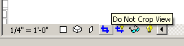
    1. Try the 'Do Not Crop View' option. This allows to paste the objects most of the time.
      image
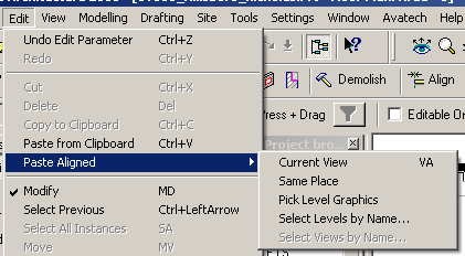
    2. Then try using the "Same Place" option for Paste Aligned. Eventhough the Revit Help file says "Same Place: Pastes the elements into the same place from where you cut or copied them.", this option works in other views too.
      image

    Wednesday, May 21, 2008

    Revitizing CAD details

    Before going any further:

    The best detail is the one created in revit using Detail components and repeating details, revit text, leaders, etc. It is always better to ‘link’ the CAD detail and draw over this CAD detail to create a full blown revit detail and then unlink the CAD detail. If you cannot do this for some reason, think again. If you still cannot do this, then:

    To do in CAD:

    • • You can skip the CAD part if you are going to fully explode the detail in Revit.
    • • Run ‘REVIT’ command (this custom command created using LISP, changes our standard DIM style; TEXT style, etc to be revit friendly. It tries to remove stacked text to regular text in DIMs, etc.)
    • • Delete unnecessary stuff. Purge.
    • • Bring objects closer to 0,0,0
    • • Set scale (this custom command created using LISP, sets DIMSCALE; LTSCALE; etc.)
    • • Use the DIM > update to update all the dimensions. This should remove all stacked text in Dimensions. (Revit 2009 does NOT understand stacked text yet!)
    • • Edit Mtext
    • • Unstack dims
    • • Mtext wrap width has to be set correctly in CAD. Because of the change in TEXT style, the width could be wrong – overlapping over drawing elements.
    • • All text within the mtext should have the same color. Revit creates separate text objects for each different colored texts.
    • • Save

    To do in Revit:

    • • Open a new project > create a drafting view in a relevant scale and import the CAD detail. Don’t import any CAD detail directly into the project file. It is just good practice!
    • • Full Explode Imported CAD detail
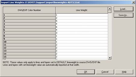
    • • Line thickness should be fine, as long as, File menu > Export/Import settings > import lineweights is setup per your office standard.
    • clip_image002
    • • Revit creates separate linetypes for each layer in the CAD dwg.  You might have to swap them to revit linetypes by selecting the objects with the filter tool. It is easy, as long as the CAD file had followed a layer standard in CAD .
    • • Text style can look a bit different. You have to swap CAD text style names to Revit text styles. Again, this is easy, as long as the CAD file had followed a standard in CAD. All leaders are exploded. You have to select and delete them and create new leaders within Revit. This is painful. The new revit leaders need to point to correct objects!
    • • Hatch may not be present; Typically you want to select the CAD hatches and swap it with Revit filled regions.
    • • Dimensions come as exploded objects. It is better to create new ones in Revit. If line is off the axis, it is difficult to dimension in Revit.
    • • None of the exploded CAD objects should have any remnants of any CAD hatch patter, text style, dwg blocks (arrow heads...!) etc.
    • • Now these objects (or the drafting view) can be copied and pasted into your project.

    As I said in the beginning, instead of going through all these steps, one could have easily created a full blown revit detail.

    Keeping the details as CAD objects, and linking them in Revit is ok as long as

    1. you have both the licenses of AutoCAD and Revit
    2. You can live with CAD details and RVT details looking little bit different
    3. You are ok fighting with Revit to make it show the CAD hatches,  stacked text, etc properly.

    Monday, February 4, 2008

    Detail plan callout tag not visible in section detail views

    Someone reported that their detail plan callout tag is not visible in their section detail views. Revit shows the tags for the callout or detail section views that are other perpendicular / intersecting views only if:

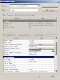
    1. The view is perpedicular and intersecting. The far clip plane (view depth) needs to encompass / intersect the detail plan callout. (this is the same parameter available in the View properties dialog box: Far clip offset.

    2. The parameter "Show in" in the View Property dialog box should be set to "Intersecting views"
    3. The parameter "Hide at scales coarser than" in the View Property dialog box should be bigger than the scale of the view you want the tag to show.