Friday, October 10, 2008

Missing Rotation Origin and active worksets

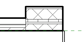
One of our project would not show the rotation origin, which looks like this,

image

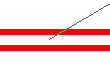
while in the rotate command. The stuff it showed looked like:
image

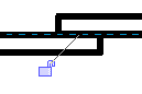
When we aligned two objects, it would not show the customary lock too:
image

No clues yet.

However, when we tried to insert windows / doors, Revit would not show any preview, but would insert them anyway. But it would not show the inserted element! Yet, it shows the opening cut made by these inserted elements!

That's the clue. The current (active) workset is switched off!!!

Thursday, October 9, 2008

Best Practices - Split Level Design

Summary:

  1. Create dedicated Revit Levels for all the change in levels in floor.

  2. Create associated views for all the Revit levels where, you envisage inserting a door / window / wall / room, etc.

  3. Whenever inserting a new element, go to the associated view for that particular Revit Level and then insert the element.

Full Story:

Drawing all the elements in a split level design on the same level (plane) looks great in plan. Until you need to elevate them or add stairs / ramps.


Adding Revit levels respective to the actual change in levels in floors would aid in making the sections / elevation look right (by selecting a wall > move to it's correct base constraint; moving the windows and doors with correct sill levels; etc.)


However, the plan may not look right, because the change in sill level of the windows raised them above the cut plane, etc.


However, you can draw "Plan Regions" (View menu > new > Plan regions) to offset this and everything will be fine.


Any wall or room added into the project automatically lands on the level the current view is associated with. And so, if you need to add a wall, etc. on the raised (lower) floor level, and if you don't have an associated view for the level, you would have to add it in a view associated with a different revit level and later select the particular object and move it to its correct level. Sometimes, if the level difference is too much, the inserted / added object will vanish in front of your eyes, with a Revit warning, because of the view range stuff. (alas, if the object you are adding is a room, you cannot change the level parameter for the room and so you are stuck!)
To circumvent this, you need to create associated views for all the Revit Levels.


To add elements to a particular level, you need to make the view associated to that level current before proceeding.

For printing purposes, you can create an overall plan with Plan Regions to show all elements along with annotations in one view.

Wednesday, October 8, 2008

View Range and cut plane revisited

I read a very nice chart posted on the web (By James Van?) explaining the view range options accessed from the View property. I could not find it anymore and had to make a similar one to explain to our people.

image

The TOP range has always been confusing. Symbolic lines / model lines of elements (for eg. windows) that are above the cut plane, but below the TOP range will show up. Seems like the view is aware of some selected objects in between these ranges, but show them only if it is designed to show inside the family. This option can be used to show upper storey windows / over the head casework.

The <Beyond> linetype can be tweaked in Settings menu > Linetypes... dialog box.

Here is a window at 3' sill level on a view with a cut plane at 4' and a TOP range of 7'-6" (default)

image

The sill level of the window is raised to 7'

image

If the sill level is raised to 8', poof...

image

The following picture shows the model lines that are used to depict the frame in the window family.

image

Tuesday, October 7, 2008

Level of accuracy

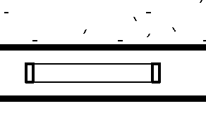
Want to create a very simple single flight stair like this:

image

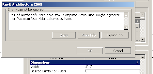
8 risers of 7" each that makes 4'-8". Perfect. But Revit kept giving this error message, when tried with 8 risers. 

image

It actually says "Desired number of Risers too small..."

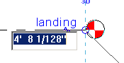
How can 8 risers be too small? Anyway, it turns out, when the accuracy of the levels was checked, it said.

image

Correcting this resolved the issue. Great!

Now, who is the culprit that actually entered such crazy dimension to that level?

Monday, October 6, 2008

Non-Align two attached walls

Very simple issue.

We have two dissimilar walls that are aligned look like this in plan:

image

image

We want to move one of the walls (brick) so that there is a 2" offset. But moving one of the walls, moves both the walls. Trying to align to a ref plane that is offset by 2", moves both the walls together too.

Selecting the wall, then selecting the Move command and then selecting the disjoin option in the option bar:

image

does the job.

image