I read a very nice chart posted on the web (By James Van?) explaining the view range options accessed from the View property. I could not find it anymore and had to make a similar one to explain to our people.
The TOP range has always been confusing. Symbolic lines / model lines of elements (for eg. windows) that are above the cut plane, but below the TOP range will show up. Seems like the view is aware of some selected objects in between these ranges, but show them only if it is designed to show inside the family. This option can be used to show upper storey windows / over the head casework.
The <Beyond> linetype can be tweaked in Settings menu > Linetypes... dialog box.
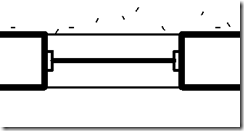
Here is a window at 3' sill level on a view with a cut plane at 4' and a TOP range of 7'-6" (default)
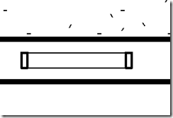
The sill level of the window is raised to 7'
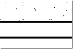
If the sill level is raised to 8', poof...
The following picture shows the model lines that are used to depict the frame in the window family.


No comments:
Post a Comment