Showing posts with label dimension. Show all posts

Monday, March 23, 2009

Show Meters in Level Dimensions

If the project is in MM and you want to show the dimensions in M in certain views, you can create a new dimension type that has its units set as M.

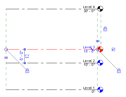
However, to change the Level dimensions in Elevation views to show in Meters, you have to edit the Level head family (look for it in the Project Browser > Families > Annotation Symbols > Level Head…).

image

In the family editor, select the ‘Elevation’ label and select in the ‘Edit Label’ button in the option bar.

image

Select the Elevation parameter in the RIGHT side of the Edit Label dialog box. (If you select the label in the LEFT side, the “Edit parameters Unit format” button - small hand like thing at the bottom – won’t become available.

image

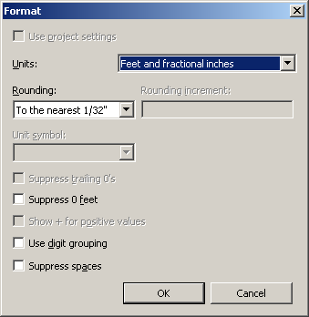
In the format dialog box, you can uncheck the ‘Use project settings’ and change the units.

image

Tuesday, September 2, 2008

Copy paste dimensions mystery

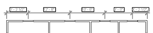
I opened a simple training file. Created a string dimension of all the windows in the level 1 view.

 image lvl 1

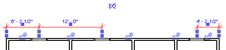
Copied all but one windows to the level 2. Copied and paste aligned the dimension string. Revit omitted the dimension that referred to the missing window. That's fine. But the dimensions stayed as a string.

image lvl 2

When I selected the dimension, Revit showed two locks for the missing dims.

Even though the dims were not visible (or there!) Revit thinks it is there.

image lvl 2

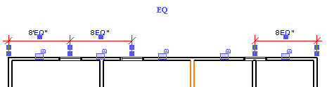
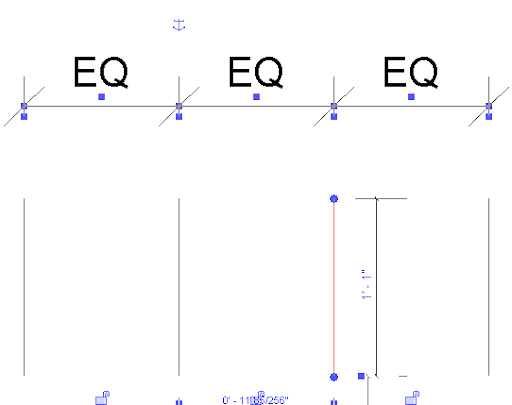
When I clicked the EQ to make them equally constrained, Revit showed this:

image  lvl 2

and an error msg that the wall conflicted with an insert...

I looked at the level 1 view....there IS the window!!!

image lvl 1

It looks like, the one of the dim witness lines on level 2 is referring to the window on the lower level (level1).

When I copied and pasted the DIM string, revit attached all witness lines that had proper references, and for any witness lines that didnt get a reference in the pasted level, Revit kept the copied from reference and also made the dims not visible!

Friday, July 25, 2008

Invisible constraints

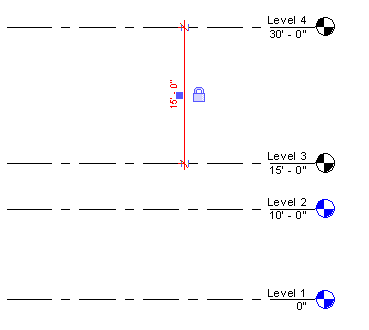
Revit allows to constrain objects. One of the ways to constrain is to dimension the objects and then lock the dimension.

image

Revit also allows one to delete this dimension, after constraining, but keep the constraint. In such a case, when you highlight a constrained object, it shows the constraint in dashed green link with a padlock.

image

Right clicking on the padlock and selecting "Show Related" highlights the constrained objects.

image

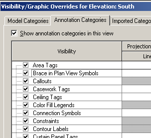
So far so good. However, if you switch off the Constraints object in the Annotation category tab in the VG dialog box, Revit does not show any clues on the constrained element.

image

May be there are other unexplained invisible constraints. If so, you might be able to solve it using this wild goose chase.

Tuesday, July 15, 2008

Equality constrain anchor

While creating a family with an equality constraint, sometimes, we want one of the elements to stay put and move the other elements based on the parameter changes. Revit has an anchor (image ) symbol that represents the object that would stay put.

When we select one of the equality constrained elements and Revit shows this symbol on the dim line. That will be the anchor line for the constrained elements. If one element is moved, all the other elements will be moved (to maintain the equality) keeping this dim line as the origin.

image

Pinning the element also gives almost the same result. We cannot move the pinned element, but an anchored element can be moved. (revit automatically switches the anchor to the neighboring element!)

Wednesday, May 14, 2008

Suppress leading 0 feet in dimension

This is a simple setting. However, a lot of people ask for this. Out of the box revit, show 0 feet in dimensions. For eg., it shows 9" as 0'-9". Some office dont show the leading 0 feet and would like revit to dimension as 9".

To change this setting for project wide:

Go to Settings menu > Project units and select Length and check 'suppress 0 feet'.  It is also a good idea to leave the rounding as 1/8" for architectural projects.

image .

To change this setting for only one dimension:

You have to create a new dimension type.

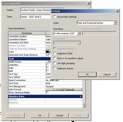
Select dimension, Go to its properties, click on 'edit/new' and then duplicate and then Units Format parameter at the bottom. You have to uncheck 'use project settings' option to 'suppress 0 feet'..

image