Tuesday, September 30, 2008

Substitute / replace families

Good old AutoCAD has a method, with which, one can substitute a block with another block. For eg., you can use the insert command and then say "blockA = c:\blockb.dwg".

image

Revit has its own family substitution. For eg., you have a Single Flush Door family in your project with various sizes (types): 36", 30" and 42".  During DD, transoms are added for all the single Flush doors. To make this correction in the model, there are (atleast) three roundabout methods and one quicker method:

  1. You can edit the Single Flush Door family and add a transom. But you already have another family in the library with the transom.
  2. You can load the transom door family from the library and then "select all instances" of the single flush door by each type and swap them with the transom door family. This is a long process and this also may require you to create the corresponding types in the the transom door family.
  3. Another method would be to rename the Single Flush Door family in the project browser to the transom door family and then load the transom door family from the library to override the existing version like
    image
    This approach brings the new door family and keeps the various types that are already present (36", 30" and 42") in the project intact.
  4. Better yet, Revit has an inbuilt functionality to do this. Right click on the Single Flush Door family in the project browser and select "Reload...";
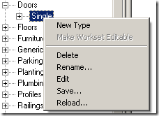
    image
    Select the transom door family; revit asks you permission to override and automatically renames the family and also keeps the family types intact!

Tuesday, September 23, 2008

View Filter differences in 2008 and 2009

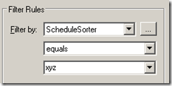
View filters behave a bit different in 2008 and 2009. We have a filter called "Filtered Objects" in our template that applies to all categories and which is Filtered By based on the following Filter Rule in RAC 2008. (ScheduleSorter Project parameter equals <nul> or any other value)

image

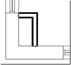
When opened in RAC 2009, the filter changes to:

image

This can cause quite a confusion, especially if the filter is used to turn on/off the visibility of the objects... based on the unwanted behavior, it can switch off all the objects in view when opened in 2009!!!

I will report this to Autodesk.

Monday, September 22, 2008

Schedule tips

Interesting thing I came across in Revit Help on Schedules today.

"Mouse-wheel scrolling is available in schedule views. Move the mouse wheel to scroll vertically. Hold SHIFT and move the wheel to scroll horizontally."

Horizontal movement is interesting!

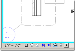
Also, the vertical scrolling does not work if a cell is selected. (Horizontal still works!)
image

You have to unselect the cell by clicking on the "grey area" or select more than one cell (by clicking on one and dragging) for vertical scrolling to work.

Wednesday, September 17, 2008

Show cut patterns for Existing Phase

Be default, the cut patterns for walls, etc. that belong to a previous phase are not shown. The cut lines are also greyed out like this:

image

The options to tweak this is here: Settings menu > Phases > Graphic overrides. Here is the default setting:

image

However, if you want to show the walls with cut patterns like this:

image

You need to tweak 2 settings in the Graphics Overrides.

1. Select the "Existing" row under "phase status", and then click on "override" under 'cut patterns' and and then click "clear overrides"
2. Select the "Existing" row under "phase status", and under 'material', select "Phase Exist" and delete it. (don't select a different material).

The Graphics override dialog should look like this:

image

That's it.

Tuesday, September 16, 2008

Design Option Visual clues

Revit comes with a lot of visual clues to represent various modes. For eg., the reveal hidden elements mode is shown like

image

The temporary hide / isolate mode is like

image

Group edit mode is like

image

However, Design option edit more just grey out the objects that don't belong in the design option.

image

Since greying out (screening out) of objects are used in architectural drawing to denote phases, existing condition, etc., a better visual clue with a border like temp hide / reveal hidden will help a lot. It will be even better if the border came up with a name of the design option being edited.

Revit help says:

To determine whether you are currently in Design Option Edit mode, check the Editing button of the Design Options toolbar.  If it appears to be pressed (instead of raised), you are in Design Option Edit mode.....To determine which design option is currently active for editing, move the mouse over the Editing button. It displays a tooltip that indicates the active option, using the following format

I wish there was a better clue.

Monday, September 15, 2008

Visibility graphics and dependent views

The Trainers conundrum:

We have model elements and then annotation elements in Revit. Annotation elements are view dependent and don't show up neither synchronized in other views. And VG is always view dependent. Great!
image

We also have dependent views, where the annotation elements are synchronized among other dependent views and are not strictly view dependent . The VG tweaks are the same for the parent and all its dependent views. However the dialog box still says "Overrides for dependent view!", which is not entirely correct.

image

Then we have this amazing ability to hide a particular object using the "Hide in View >Elements" option in the right click menu:

image

This hides the object only in that view and not in it's synchronized dependent / parent views. Even though this looks little counter intuitive, this behavior is very useful.

Friday, September 12, 2008

Crop region and Annotation crop

Here is a view that has annotation crop shown in green; the view crop is shown but the view is not cropped.

image

After the view is cropped, it looks like:

image

The View crop (boundary) crops the

  • model elements
  • detail components
  • repeating details
  • filled regions
  • Insulation, etc.
  • detail lines

It does not crop:

  • annotation tags
  • Text objects

The annotation crop crops both the text and annotation tags.

Dimensions - get cropped by both the view crop as well as the anno crop. If any one of the witness points of a DIM is not within the view crop region, then Revit does not show that particular string. And if the DIM string extends beyond the anno crop, it is not shown.

image

If we want to draw anything outside the view crop boundary, it is not possible. (One can draw stuff on sheet!) There may not be any circumstances that require it. However, Revit allows us to draw Revision clouds outside the boundary. (Thank God!)

image

Quite nuantic!

Tuesday, September 9, 2008

Multiple Tags

Whenever we tag an object with Revit, for eg. a door, it does not allow us to create two tags for the same object.

However, if we finish the command (by clicking image ) then Revit allows us to tag the same object again.

image

This may not seem to be of much use, but if you tend to draw a bunch of revision clouds in the same command,

image

then you might be able to tag individual revision clouds one by one (after clicking the modify button, of course).

image

Monday, September 8, 2008

Noteblock vs Schedules

Can the Noteblock command be built inside the schedule command?

Noteblocks are grouped inside the schedule set in the Project Browser.
image

This misleads users to try to create a schedule of annotations using the schedule command.

I feel this distinction is not needed. Inside the Schedule creation command one could select Model or Annotation elements to schedule elements accordingly. 
image

(Or revit should group the noteblock separately in the project browser?)

Wednesday, September 3, 2008

Stairs and Handrail balusters termination

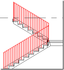
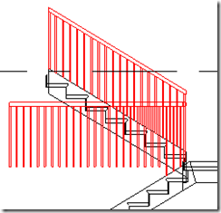
When we create a stair, the balusters get terminated by the stringer by default like this:

image

When we flip the railing with the image control, the balusters terminate at the treads. Which is nice!

image 

Editing the sketch using the image button, and moving the railing line inside the stair width also results in the same scenario.

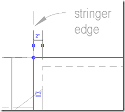
However, when we move the railing line outside the stair width, it looks like:

image

Changing the options available in the options bar like

image

does not solve this. Aligning the sketch with the stringer corrects it.

image

Tuesday, September 2, 2008

Copy paste dimensions mystery

I opened a simple training file. Created a string dimension of all the windows in the level 1 view.

 image lvl 1

Copied all but one windows to the level 2. Copied and paste aligned the dimension string. Revit omitted the dimension that referred to the missing window. That's fine. But the dimensions stayed as a string.

image lvl 2

When I selected the dimension, Revit showed two locks for the missing dims.

Even though the dims were not visible (or there!) Revit thinks it is there.

image lvl 2

When I clicked the EQ to make them equally constrained, Revit showed this:

image  lvl 2

and an error msg that the wall conflicted with an insert...

I looked at the level 1 view....there IS the window!!!

image lvl 1

It looks like, the one of the dim witness lines on level 2 is referring to the window on the lower level (level1).

When I copied and pasted the DIM string, revit attached all witness lines that had proper references, and for any witness lines that didnt get a reference in the pasted level, Revit kept the copied from reference and also made the dims not visible!